|
|
CHAPTER 14 - MEASUREMENTS IN PRESSURE CONDUITS
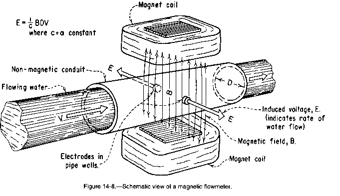
The operation of magnetic flowmeters is based upon the principle that a voltage is induced in an electrical conductor moving through a magnetic field. In the case of magnetic flowmeters, the conductor is the flowing water being measured. For a given field strength, the magnitude of the induced voltage is proportional to the velocity of the conductor.
The meter consists of a nonmagnetic and nonelectrical conducting tube or pipe through which the water flows. Two magnetic coils are used, one on each side of the pipe. Two electrodes in each side of the insulated pipe wall sense the flow-induced voltage. The meter should be mounted so that the electrodes are horizontal to prevent air from breaking the voltage measuring circuit. The meter has electrical circuits to transform the induced voltage into a rate-of-flow indication on a meter dial (figure 14-8). The electrical sensing system and uniform flow-through passage allow the magnetic flowmeter to measure flow in both directions.
|
|
A source of electrical power is needed to activate the magnetic field, and a transmitter is used to record or send the rate-of-flow signals to desired stations. The water needs sufficient conductivity, but other properties such as temperature, viscosity, density, or solid particles do not change calibration. However, dissolved chemicals can deposit on the electrodes and cause accuracy errors. Some of these meters are provided with wipers or electrolytic or ultrasonic electrode cleaners.
Head losses through the meter are negligible, and accuracy of measurement in the upper half of the meter's rated capability is usually good. Later model electromagnetic meters can have good accuracy (+/-1.0%) for a range of minimum to maximum discharge.