|
|
CHAPTER 10 - CURRENT METERS
6. Current-Meter Stations and Handling Equipment
The essential components of a current-meter station are a water-level gage (stage recorder), a bench mark, fixed measuring points in the channel cross section, and a stay line to hold the meter in the measuring plane or cross section under high velocity and deep water. Water stages or elevations can be obtained by nonrecording gages or water-stage recorders. The gage types most commonly used in irrigation water measurement are the graduated, enameled, vertical staff, hook, and float. A commonly used staff gage is shown on figure 8-4 in chapter 8. Float gages are often connected to water stage recorders that produce charts of the water surface variations against time. The benchmark should be conveniently and permanently located, with the elevation of the gage datum carefully referenced to the benchmark.
Velocity measurement points should be located in a cross-section plane which is oriented perpendicular to the channel flow. Where the channel is shallow enough to permit wading measurements or where cable-supported measurements are taken, a tagged wire should be used to establish the measuring points. When measurements are made from a bridge, permanent measuring points should be established upon the bridge. The measuring points should be permanently marked at equal intervals of from 2 to 10 feet (ft), depending upon the width of the stream or canal. If the stream velocity is high or if the structure from which the measurements are being made is far above the water, a stay-line can be used to pull the current meter back into the plane of the measurement cross section. A cable supporting a traveling pulley can be stretched across the canal upstream from and parallel to the measuring cross section. The traveling pulley is fitted with a swiveling stay-line pulley. The stay-line runs from the meter hanger, through the swiveling pulley, and back to the operator at the measuring station. The support cable is placed perpendicular to the flow velocity and far enough upstream so when the current meter is pulled back into the vertical plane at the measurement station, the slope of the stay-line relative to the water surface is flatter than 30 degrees.
Streamlined weights with large tail fins, commonly called Columbus or C-type weights, are used to carry the meter down into the flow and help hold it in the desired position when measurements are being made from a bridge or a cable. Weights are available in 15-, 30-, 50-, 75-, 100-, 150, 200-, 300-, and 500-pound (lb) sizes. Usually, weights of 75 lb or less are adequate for canal and small stream measurements. To handle the relatively heavy current-meter and weight assembly, the type A portable crane shown on figure 10-4 is used. This crane is mounted on three wheels designed to hold the current meter and weight in a balanced position while moving between measuring points. For stream measurement, the crane is tilted to lean against the bridge rail so the boom supports the meter and weight clear of the bridge. The meter is raised and lowered by a crank and cable reel on the frame. The crane may be folded into a compact unit for ease in transportation.
A cable device used extensively to position current meters across canals is shown on figure 10-6. The head tower with the operating mechanism for the cable and the tail tower on the opposite bank can be fixed installations, or vehicles may function as anchors on each side of the canal. A counter on the head tower reel determines the lateral position of the traveling block. Another counter on the reel raises and lowers the meter and determines meter depth. The entire installation is relatively inexpensive and permits stream gaging to be done safely and easily from the bank.
|
|
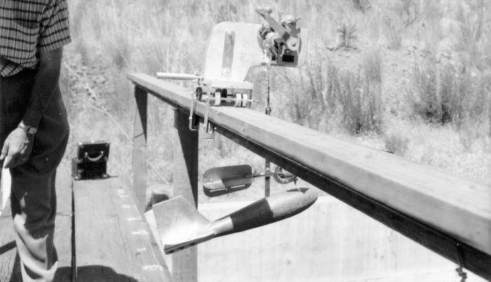
A carriage and track system to handle current meters with heavy weights when working from bridges is shown on figure 10-7. The standard reel and counter assembly is mounted on a carriage supported by ball-bearing rollers that run on a 2- by 6-inch (in) timber track permanently mounted on the bridge rail. This equipment allows the operator freedom of movement with safety, facilitates obtaining accurate stream gaging data, and is easily portable from one station to another.
|
|