|
|
CHAPTER 9 - SUBMERGED ORIFICES
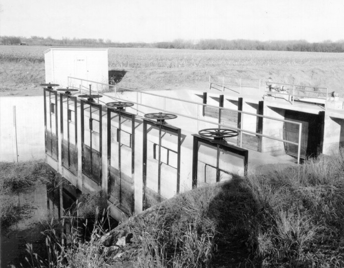
Occasionally, at a given site, the canal water surface level should be checked up to a specified elevation while simultaneously measuring the rate of flow. The combined checking and measuring functions can be provided by orifice check structures which are built into the canals as in-line structures (figure 9-7). One or more orifice openings of the necessary size are constructed in the lower portion of a wall that extends across the canal at the upstream end of the check-type structure. These orifices are used to measure the discharge. A second wall with one or more gated openings is constructed at the downstream end of the structure. This downstream control is used to check the canal water surface to the desired elevation. Two stilling wells are located outside of the structure. One is connected to a piezometer in the canal upstream from the orifice wall, and the other is connected to a piezometer in the basin between the upstream and downstream walls. In small orifice check structures, staff gages are used in place of piezometer and stilling wells. In either case, the differential head acting across the orifice can be determined, and with knowledge of the orifice dimensions and characteristics, the rate of flow can be determined.
|
|
The coefficients of discharge that should be used to compute the rate of flow are difficult to determine analytically because of different degrees of suppression at the bottom and sides and between the orifice openings. Computed discharge tables are ordinarily provided for each structure, but usually a statement is included that a field rating is necessary to ensure accurate results. In general, the recommended practice is that field ratings be made by current meter data and that discharge curves be prepared. For maximum potential accuracy, care must be exercised to prevent either excessively small gate openings or small differential head readings that cause large errors of precision of head or gate opening effects on discharge measurement.