|
|
CHAPTER 5 - INSPECTION OF WATER MEASUREMENT SYSTEMS
10. Poor Installation and Workmanship
Contrasting with the measurement devices that were once accurate and dependable but have deteriorated are those that, because of poor workmanship, were never installed properly. This category includes devices that are installed out of level or out of plumb, those that are skewed or out of alignment, those that have leaking bulkheads with flow passing beneath or around them, and those that have been set too low or too high for the existing flow conditions. Inaccurate weir blade lengths or Parshall flume throat widths, insufficient or nonexistent weir nappe ventilation, or incorrectly located and zeroed head or staff gages cause measuring errors.
A transverse slope on a sharp-crested weir blade can cause errors, particularly if the gage zero is referenced to either end. The error can be minimized by determining the discharge based on the head at each end and using the average discharge. Errors in setting the gage zero are the same as misreading the head by the same amount. At low heads, a relatively small zero setting error can cause errors of 50 percent or more in the discharge. A head determination error of only 0.01 ft can cause a discharge error of from 5 percent on a 90degree V-notch weir to over 8 percent on a 48inch (in) Cipoletti weir (both for a head of 0.20 ft). The same head error on 6 and 12in Parshall flumes can result in 12- and 6-percent errors, respectively, for low heads.
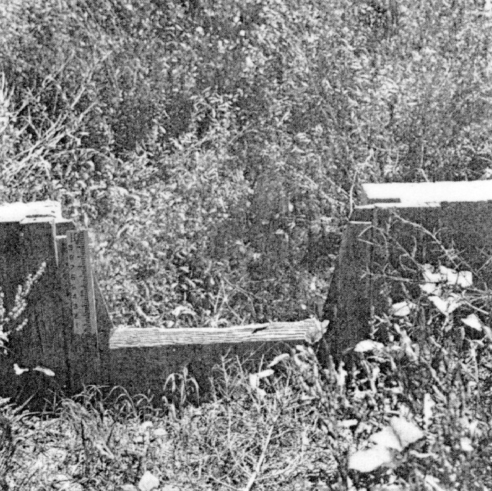
Out of plumb or skewed weir blades will show flowmeasurement inaccuracies of measurable magnitude if the weir is out of alignment by more than a few degrees. Rusted or pitted weir blades or those having projecting bolts or offsets on the upstream side can cause errors of 2 percent or more depending on severity of the roughness. Any roughness will cause the weir to discharge more water than indicated. Rounding of the sharp edge of a weir or reversing the face of the blade also tends to increase the discharge. On older wood crests, a wellrounded edge can cause a 15- to 25-percent or more increase in discharge (figure 5-8). The well-rounded edge on the once sharp-crested weir on figure 5-8 will increase the discharge to well above "standard." The weeds are also undesirable, as is the weir gage which projects into the flow area.
|
|
Certain types of meters require pressure readings to determine discharges. Piezometers, or pressure taps, as they are sometimes called, must be regarded with suspicion when considering flow measurement accuracy.
Piezometers or pressure head taps must be installed with care and with a knowledge of how they perform; otherwise, indicated pres-sure values can be in error. For example, as shown on figure 5-9, the four piezometers indicate different pressure readings (water levels) because of the manner in which flow passes the piezometer opening. Piezometer openings are shown larger than they should be constructed in practice. Always use the smallest diameter opening consistent with the possibility of clogging by foreign material. Unless the piezometer is vertical as in Y, the water elevation will be drawn down as in X or increased as in Z. Basically, pressure taps should be perpendicular to the flow boundary, and the flow must be parallel to the boundary. Rough edges or burrs on or near the edges of the piezometer holes deflect the water into or away from the piezometer, causing erroneous indications. The case as in W shows the tube pushed into the flow, causing the flow to curve under the tip which pulls the water level down. Errors caused by faulty piezometer tap installation increase with velocity.
|
|
Sometimes, to obtain a better average pressure reading, four taps around the pipe are manifolded. If unbalanced pressure exists because of velocity distribution, error can be introduced by flow circulation in the manifolding tubing. Two forms of manifolding are shown on figure 5-10. The commonly seen case (a)-circular form-causes circulation errors. Case (b) is the triple tee system, designed to minimize circulation errors. Large tube diameter relative to piezometer hole diameter through the meter wall will reduce circulation error considerably for both cases.
|
|
Frequently, pressure taps are connected to manometers and Utubes (figure 5-11), and air trapped in the tubing can cause large errors. Air travels in bubbles that tend to rise and form large air blockages. Thus, piezometers should not be connected at the top of a pipe. Even with taps on the side, air will come out of solution as water warms. Air in the vertical parts of the tubing causes large errors. Although air in horizontal parts of the tubing does not cause error, a bubble will likely move to a vertical part of the tubing when flow increases or decreases. For bleeding air, flowmeters should be placed at locations where the pipelines are under positive pressure; that is, where the hydraulic grade line is well above the pipe and manometry system as shown on figure 5-11.
|
|
If the meter and/or manometer are above the grade line as shown on figure 5-12, then pressure is negative. Negative pressure causes air to come out of solution and accumulate. Also, air can leak through pipe fittings and flange gaskets into the pipe and manometer system. Air can leak through openings that water cannot leak through.
|
|
Care in designing the system should be taken to make sure that the hydraulic grade line is above the tubing system at maximum water delivery. Otherwise, bleeding will have to be done frequently with separate water source purging, or water delivery will have to be shut off to provide positive pressure during bleeding. When the hydraulic grade line is below the system, the negative pressure causes air to accumulate faster. This condition should be avoided if at all possible.
The effect of a few deficiencies often found in measuring devices has been given to illustrate the degree of error to be expected in making ordinary measurements under ordinary conditions. Other effects have not or cannot be stated in terms of percent error without an exact definition of the degree of fault or deterioration. The examples given should be sufficient to emphasize the importance of careful and exact installation practices as well as regular and prompt repair or rehabilitation of the devices after they have been installed.